Can you cut LED strip lights? Yes. Most low-voltage LED tape supports cutting at the marked cut lines. These marks separate complete electrical circuits, so cutting elsewhere can disable LEDs or damage the next circuit group.
Before you cut, check the strip’s voltage, width, conductor layout, control type, and location rating. Confirm whether you have single-color, tunable white, RGB, RGBW, COB, or addressable tape. Any connector must match the tape width, contact count, and pad order.
Always disconnect the power supply before measuring, cutting, or connecting LED tape. Most beginners can handle a plug-in, low-voltage installation. Hire a licensed electrician for hardwired drivers, junction boxes, new circuits, or line-voltage work.
Can You Cut LED Strip Lights Anywhere?
No. Cut standard LED tape only on the designated line, which usually crosses exposed copper pads and includes a scissors symbol. The spacing depends on voltage, LED density, circuit design, and control type.
For example, many 12-volt single-color strips divide their LEDs into groups of three. Some 24-volt products use longer circuit groups. COB tape often provides closer cut points, but you must follow the markings on the specific product.
You can also cut many addressable strips. However, each section must retain a complete pixel circuit. Follow the printed arrows so the controller sends data into the input end of each segment.
Line-voltage rope lights and flexible neon products follow different rules. Some allow cuts only at widely spaced intervals and require specific rectifiers, end caps, and sealants. Never cut a line-voltage lighting product unless its instructions expressly allow it.
| Strip type | Typical conductors | What must align | Main cutting concern |
|---|---|---|---|
| Single-color | Positive and negative | Polarity and tape width | Cut through the center of the copper pads |
| Tunable white | Common power, warm white, and cool white | All channel labels | Reversed channels can swap or disable color-temperature control |
| RGB | Common power, red, green, and blue | Four contacts in the correct order | A shifted connector can cause missing or incorrect colors |
| RGBW | Common power and four color channels | Five contacts and the correct tape width | An RGB connector cannot carry the separate white channel |
| Addressable | Power, data, and ground; some designs add a conductor | Voltage, pin order, and data direction | The controller signal must enter at the segment’s input end |
| Water-resistant coated tape | Varies by lighting type | Contacts and restored end sealing | Cutting opens the factory coating |
Tools and Materials for Cutting LED Tape
The basic job needs only a few hand tools. However, the connector and power supply must match the strip. Read the tape markings or product documentation to confirm whether it uses 5, 12, 24, or another voltage.
The power supply output voltage must match the LED strip voltage. Its wattage rating must also cover the connected load without continuous operation at its limit. Choose a UL- or ETL-listed power supply that suits the installation location.
Use damp-location-rated components in kitchens, laundry rooms, and other damp spaces. Outdoor installations need components rated for wet locations. An IP65 enclosure resists water jets under test conditions, but it does not support submersion.
Cutting coated tape opens its protective layer. Use the manufacturer’s end cap and compatible sealant to restore the seal. Follow the product instructions because an IP rating alone does not confirm suitability for every outdoor installation.
- LED strip with visible manufacturer-designated cut marks
- Matching low-voltage LED power supply or driver
- Sharp scissors for uncoated tape, or the manufacturer’s recommended cutting tool
- Tape measure or rigid ruler
- Fine-tip permanent marker or painter’s tape
- Matching solderless connectors
- Temperature-controlled soldering iron, suitable wire, and solder if making soldered joints
- Wire strippers for pigtail connectors or lead wires
- Isopropyl alcohol and a lint-free cloth
- Aluminum LED channel and diffuser where heat control or physical protection matters
- End caps and compatible sealant for coated strip
- Low-voltage cable rated for the installation location
Skill level: Beginner for exposed, plug-in low-voltage strips. Soldering and planning long runs require more experience. Never handle the copper contacts while the system has power.
A short across adjacent pads can damage the controller or power supply. High-output tape also generates heat, so do not leave it coiled during an extended test. Unroll it and place it flat for a brief functional check.
For a permanent installation, aluminum channel helps transfer heat and protects the flexible circuit board. Avoid sealed housings unless the strip and enclosure support that use. Trapped heat shortens LED, adhesive, and power-supply life.
How to Cut and Reconnect LED Strip Lights
-
Disconnect all power. Unplug the power supply from the receptacle. If possible, disconnect the strip from its controller as well. Confirm that the LEDs and controller indicators have turned off.
-
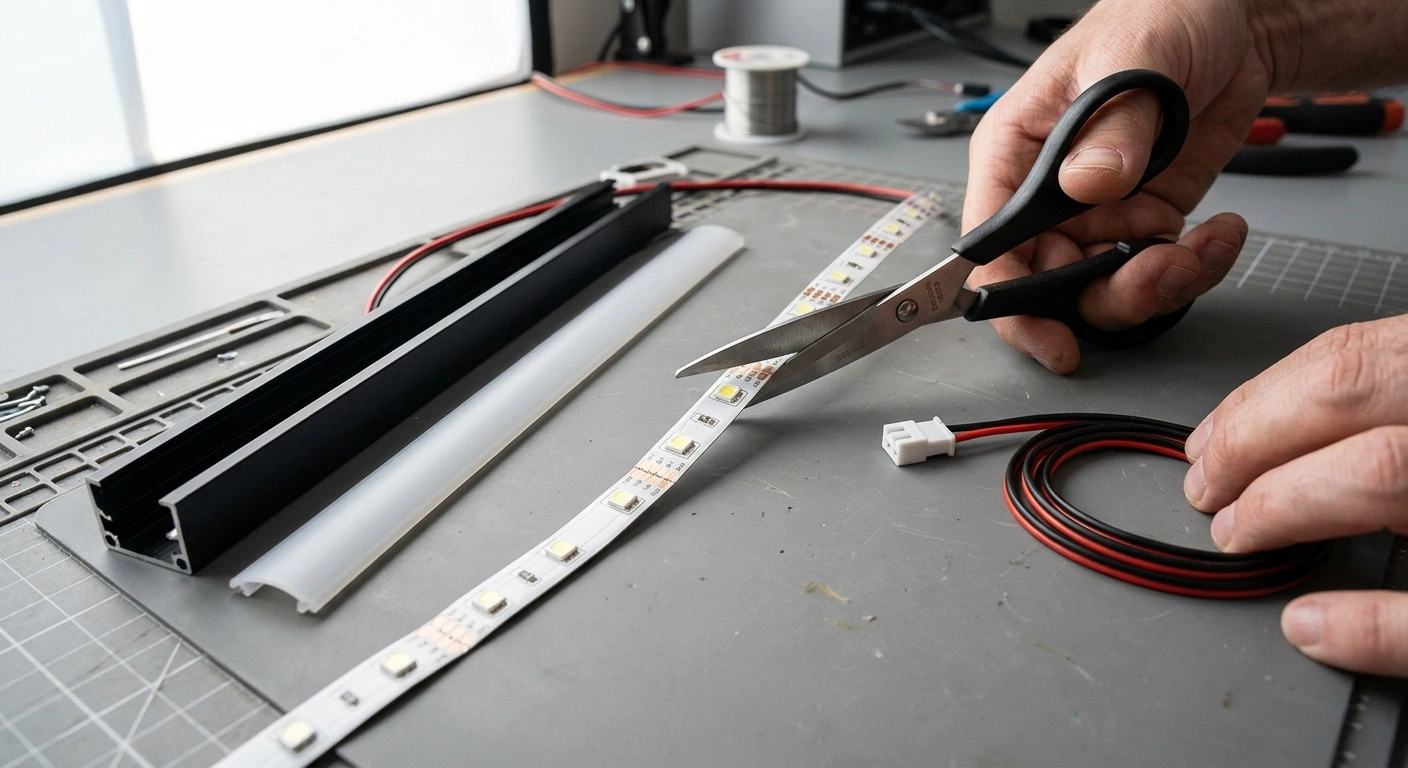
Find the correct cut mark. Look for a scissors symbol or straight line across exposed copper pads. Make sure complete pads will remain on both sides. Never cut through an LED, resistor, or control chip.
-
Measure the mounting path. Include corners, connector bodies, channel end caps, and wire jumpers in the measurement. Compare the measurement with the available cut points. The finished section may need to sit slightly short of the full space.
-
Mark the chosen line. Place a small mark beside the factory cut line without covering the contacts. Confirm that you marked the center between two circuit sections, not the nearest LED.
-
Make a straight cut. Use sharp scissors and cut squarely through the center of the copper pads. Do not twist or crush the flexible circuit board. Both cut ends should have clean, even contact areas.
-
Expose coated contacts if necessary. Remove only the amount of silicone or coating specified by the connector manufacturer. Avoid scraping through the copper. Each pad should remain flat and electrically separate from its neighbor.
-
Attach the connector or lead wire. Slide the tape fully into the connector and center each contact over its pad. For soldered joints, use minimal heat and follow the labels. Match positive, negative, color channels, data, and ground exactly.
-
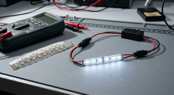
Run a short test. Lay the tape flat on a nonconductive surface before reconnecting power. Check for even light and correct color control. Gently move the connector and watch for flickering.
-
Reseal exposed ends. In damp or wet locations, fit the specified end cap and apply compatible sealant. Keep sealant from bridging adjacent contacts. Cover all exposed copper and openings in the coating.
-
Mount the strip. Clean and dry the surface before applying the tape or installing it in channel. Keep bends gentle and secure the cable separately. The cable should not pull against the connector.
Choosing the Right LED Strip Connector
Solderless connectors save time, but they must fit the tape exactly. Match the connector’s internal width to the strip width. Common sizes include 8 mm, 10 mm, and 12 mm, although other sizes exist.
Next, count the copper contacts. A two-contact connector suits many single-color strips, while RGB tape commonly needs four contacts. RGBW tape usually needs five, and tunable-white or addressable products follow their own layouts.
Do not rely on contact count alone. Check the printed labels and their order. Two strips may use the same number of conductors but assign them differently.
Coated strips often need connectors designed for coated tape. Some products require you to remove a small section of coating first. Follow the connector instructions to avoid weak contact pressure or damaged pads.
Planning Power, Dimming, and Longer Runs
Cutting a strip changes its length and total power draw. It does not change the required voltage. Calculate the load from the manufacturer’s watts-per-foot or watts-per-meter rating.
For example, a 10-foot strip rated at 4 watts per foot draws 40 watts. Choose a power supply that provides sufficient capacity at the strip’s specified voltage. Follow the manufacturer’s sizing guidance and any required operating margin.
Never connect strips with different voltage requirements to one output. A larger power supply also will not correct voltage drop. Voltage drop comes from resistance in the strip conductors and feed wires.
Long runs may look dimmer or shift color near the far end. Divide them into shorter parallel runs when possible. You can also use heavier low-voltage feed wire or inject power at manufacturer-approved points.
Plan power injection carefully. Every injection point must use the correct voltage and polarity. Addressable systems also need a shared ground between the controller, strip, and power supply.
Dimming must match the system design. Many plug-in strips use a low-voltage PWM controller between the power supply and tape. Hardwired systems may use a driver that supports a specific wall-dimming method.
Use an LED-rated dimmer that the driver manufacturer identifies as compatible. An incompatible dimmer can cause flicker, buzzing, poor low-end control, or incomplete shutoff. Ask a licensed electrician to install wall dimmers, hardwired drivers, junction boxes, and new line-voltage connections.
Keep the power supply ventilated. Do not cover it with insulation or place it in a sealed cabinet unless its listing permits that installation. Follow its clearance and temperature requirements.
How to Turn Corners Without Damaging LED Tape
Do not crease LED tape across its circuit traces to make a 90-degree turn. A sharp fold can crack the copper, even if the strip passes its first test. Instead, cut at the nearest approved line and bridge the corner.
Use a matching corner connector or a short length of soldered wire. The connector must fit the tape width, contact count, and pad arrangement. Remember that connector bodies take up space inside shallow aluminum channels.
For addressable strips, maintain the printed data direction through each jumper. Test every channel before installing the diffuser. While testing, move the joint gently to reveal an intermittent connection.
Troubleshooting a Cut LED Strip
Most post-cut failures come from incorrect cut placement, poor connector alignment, reversed polarity, or damaged pads. Disconnect power before inspecting any joint. Restore power only for a controlled test.
Work from the power supply toward the unlit section. Check each connection in order instead of replacing parts at random. Stop immediately if the power supply cycles, overheats, smells damaged, or makes unusual electrical noise.
| Problem | Likely cause | Fix |
|---|---|---|
| The entire cut section stays dark | Reversed polarity, poor contact alignment, incorrect voltage, or an off-mark cut | Disconnect power, verify voltage and polarity, then reseat the connector. If possible, recut at the next marked line. |
| Only part of the strip lights | A cut interrupted a circuit group, a trace has damage, or a later joint has opened | Remove the damaged interval at approved cut lines and reconnect the sound sections. |
| One RGB or RGBW color fails | A connector contact has shifted, collected contamination, or reached the wrong channel | Realign each contact with its labeled pad. Confirm that the connector supports every channel. |
| The strip flickers when touched | The solderless connector is loose or the tape does not sit fully inside it | Open the connector and insert the tape again. Cut a fresh square end or solder the joint if necessary. |
| The far end looks dim or shows the wrong color | Voltage drop along a long run or undersized feed wire | Use parallel feeds or approved power injection with properly sized low-voltage cable. |
| An addressable segment behaves unpredictably | Reversed data direction, no shared ground, or an incorrect controller protocol | Follow the direction arrows, connect all grounds, and verify the pixel type in the controller settings. |
| The adhesive releases | Dust, grease, heat, texture, or bending stress has weakened the bond | Clean the surface and use aluminum channel with suitable clips or channel adhesive. |
| Moisture appears inside coated tape | The cut opened the seal or the end cap failed | Disconnect and dry the assembly. Replace corroded tape and reseal it with the specified parts. |
Cut LED Strip Lights Safely at the Marked Points
So, can you cut LED strip lights safely? Yes, if the manufacturer provides designated cut points and allows the product to be shortened. Each remaining section needs a complete electrical circuit.
Match connectors by voltage, width, contact count, polarity, and control type. Test every joint before mounting the tape or closing the diffuser. Restore the seal on coated strips and use location-rated components around moisture.
Avoid sharp folds, manage voltage drop, and provide ventilation for the power supply. Aluminum channel can improve heat transfer and protect frequently handled tape. Leave hardwired drivers, junction boxes, new circuits, and line-voltage flexible lighting to a licensed electrician.